Welcome To Smith Racecraft
We Motivate
The Online Shopping System is currently being upgraded.
To place orders please call: (214) 330-0660
To place orders please call: (214) 330-0660


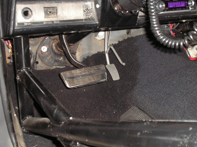
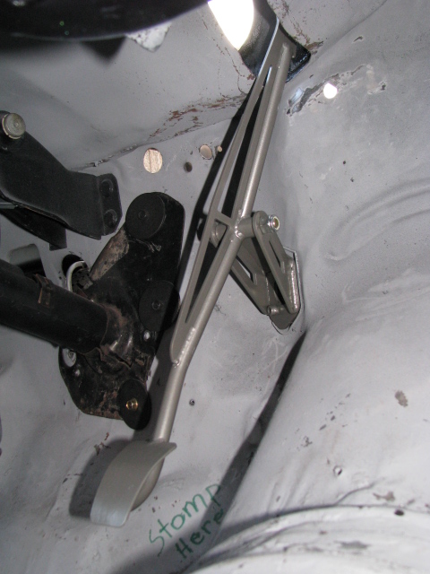
Remove the cowl panel and stock gas pedal with all associated parts.
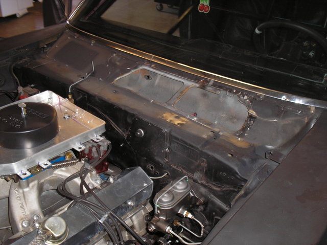
Move any wires or objects that are in the ear of the pedal under the dash. Disassemble the new pedal.
Use a drill and 9/64" drill bit to drill out the stock holes in the firewall.
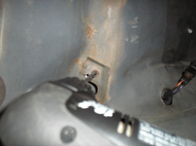
Take an air grinder and sanding disc to smooth the hole flush.
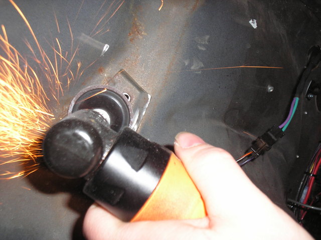
Install the main bracket. A magnet will help hold it in place if you're working solo.
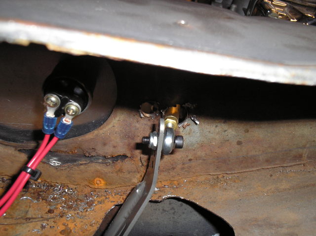
Climb back out of the car and install the backing plate. A 7/16" wrench is all you need as the bolts have been tig welded to the bracket.
The top of the pedal needs to go through the lower cowl. An air powered saw is the tool for this job.
Note: Hole does not need to be this big, just big enough for pedal to fit through.
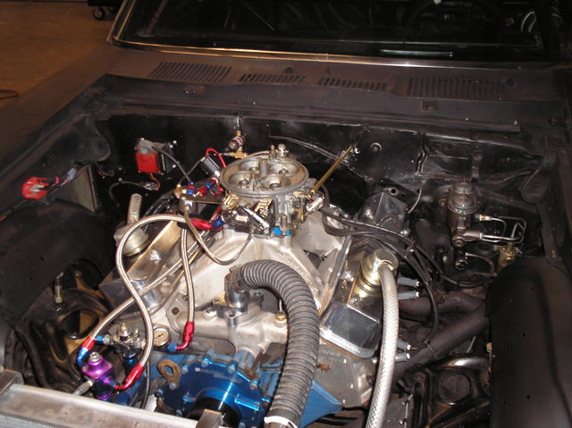
You need to drill a hole in the firewall so that the throttle rod and join the carb and pedal.
[
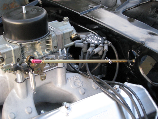
Now you are going to need an extra hand. To adjust the rod you need to mash the pedal while someone else opens the carb to full throttle and pushes a pin through the appropriate holes when they line up.
That's it you're done, reassemble everything!

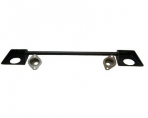
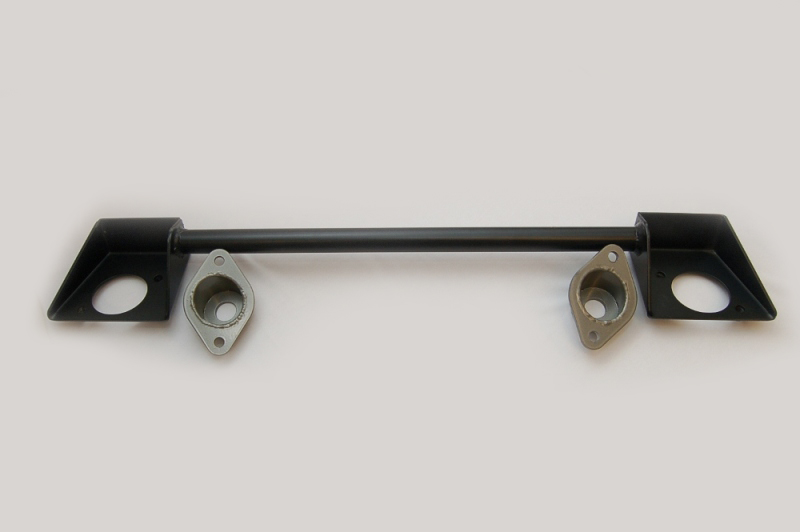
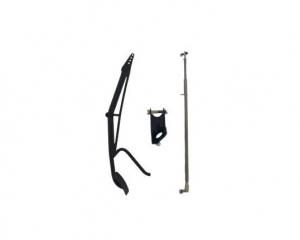
Kit Consists of: 7 Pieces
Tools required:
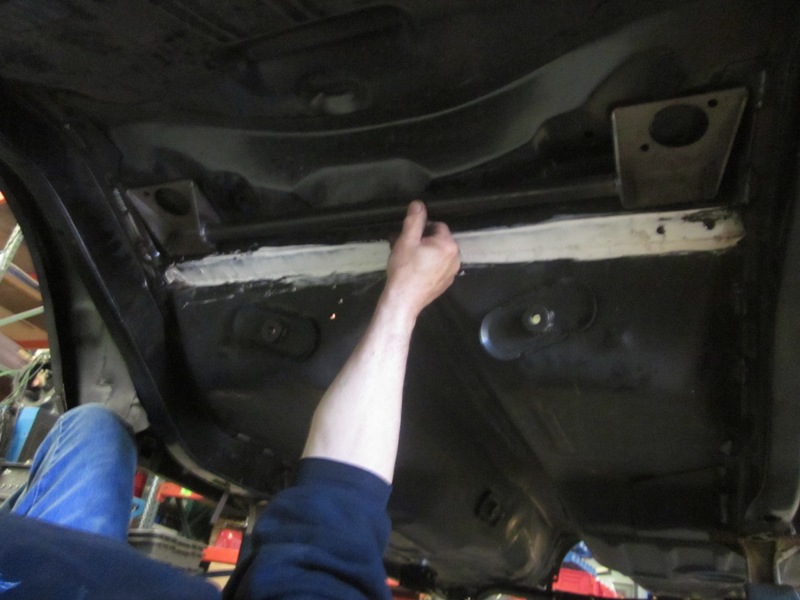
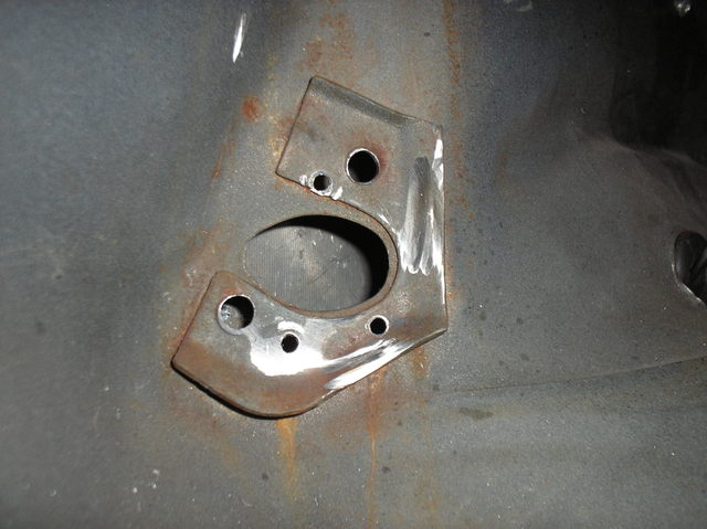
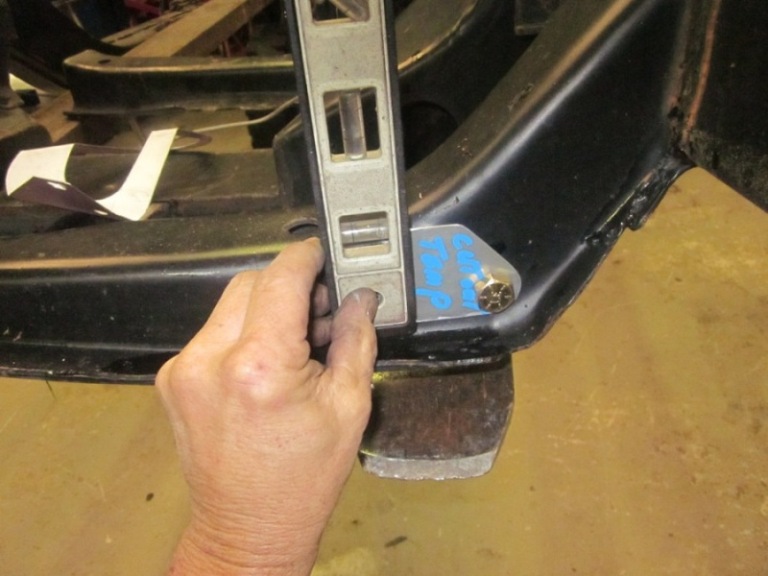
Center Bracket per picture in pocket flush against vertical body panel
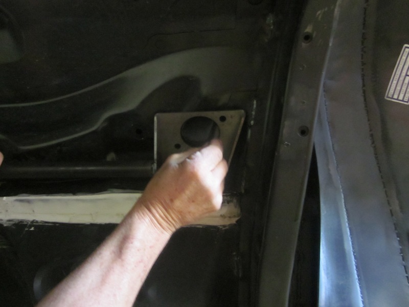
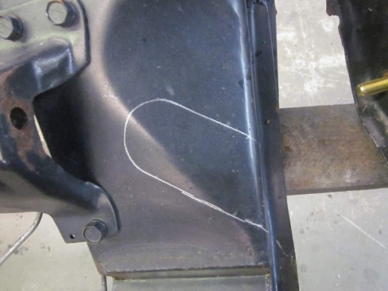
Mark large holes for cutting on body
2ea. ¾ holes per side ( Bolt Location)
1ea 2 ¼ hole per side ( Top shock mount)
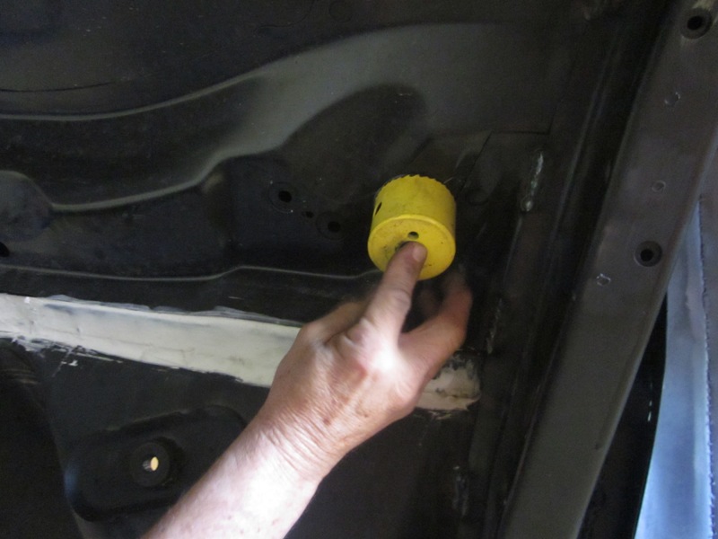
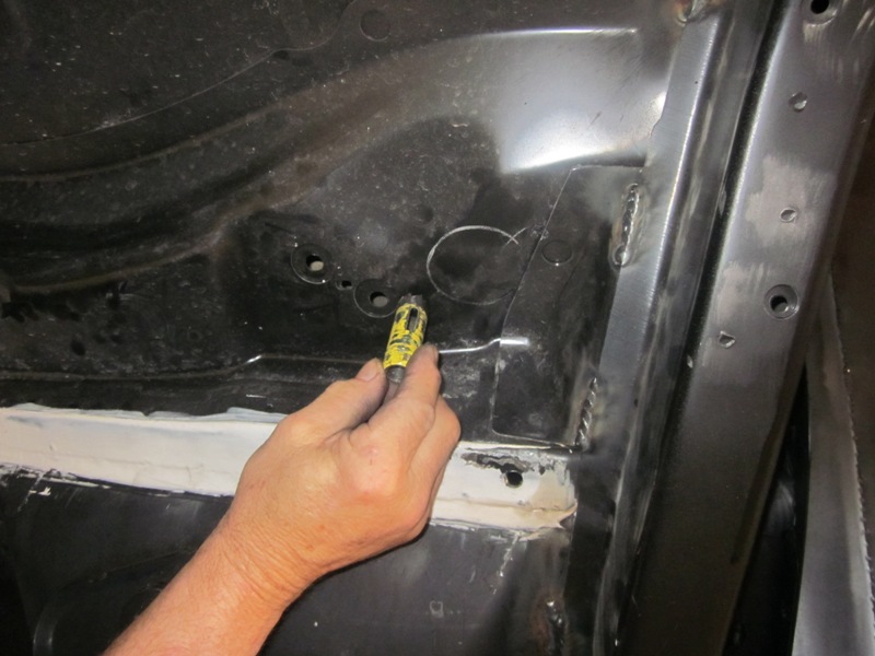
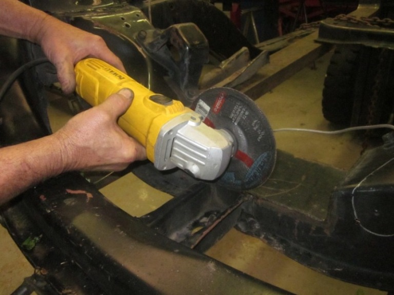
Cut holes both sides. You will not be cutting into the factory pocket as you can see in the trunk. You do not need to cut out the floor any more than the first panel cut.
Weld Square MetalShock Pockets ( Tig or Wire)
Small Stich Welds around square shock mount brackets is enough.
Note: The round tube does not have to be welded as it’s merely a locating and brace device.
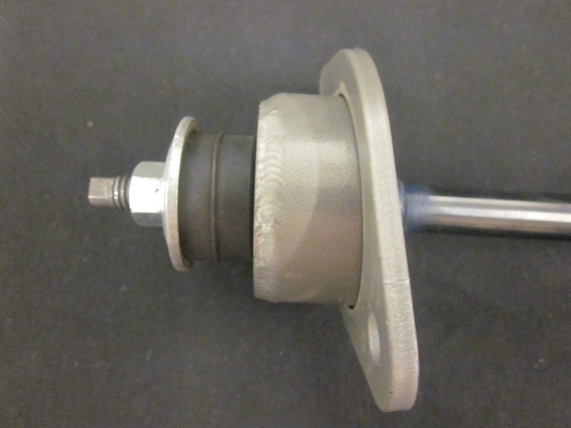
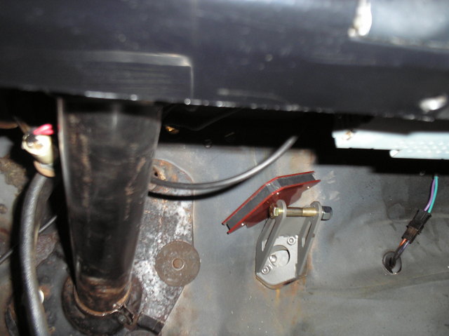
Install cup over shaft of shock with busing above and below shock cup. Tighten per shock instructions and put shock up into the new body hole and thread the two supplied bolts to secure upper shock rod.
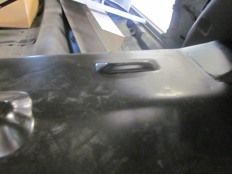
Clarification: The welded nuts on the back will now go up into the pocket where you can thread your shock plate into. The large hole you have just drilled is where the top of the shock is contained. (This facilitates getting the shock as high as possible in the car without protruding into the car)
Install the cups so they are angled correctly towards the lower spring perch which should contain a lower shock mount tab. You may have to add spacer to the tab or cut away some part of the tab so the shock can adapt to your lower perch. Since there are so many spring/shock mounts out in the market, sometimes the lower mount has to be modified unless it’s ours.
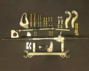
67-69 Camaro/Firebird, 68-74 Nova
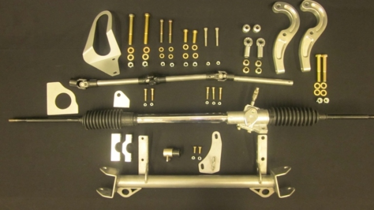
Rack & Pinion
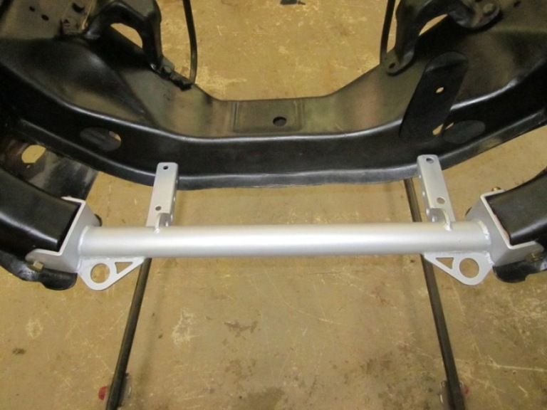
Rack & Pinion Mount Assembly (Left Side)
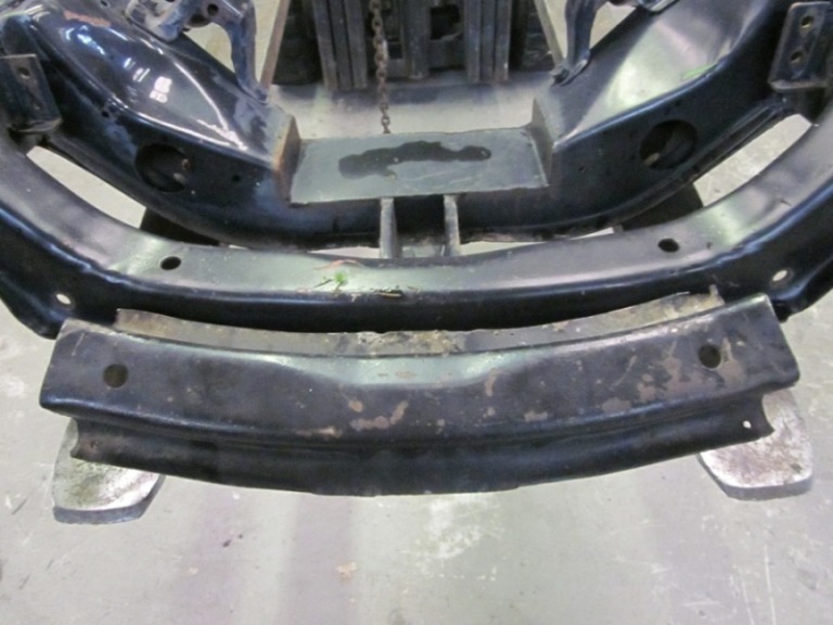
Cross member: 1 ea.
U Joints: 3ea
Steering Shafts: 3 ea.
Steering Arms: 2 ea.
Steering bracket 1 ea. (goes on frame)
Steering Tube Mount 1 ea.
Rod ends 2 ea.
High Mis-alignment bushings 4 ea.
Stock A arms will take 4 ea. 5/16 thick (not included in kit)
Tubular A arms will take 2ea 5/16thick and 2ea 13/16 thick (not included in kit)
Bolt Kit:
½ x 4” 2 ea.
3/8 x 3 ¼ “ 2 ea.
7/16x 1 ½ 2ea
5/16x 2 ¼ 2ea
¼ x 1 ½ 6ea
¼ x ¾” 2ea.
½ x 3 1/2” 2 ea.
Washers and Locknuts as required.
2 ¼ Hole Saw
Cut off Wheel
Assorted Socket/Wrench’s as required for typical bolts
Note: May Have to Lift Engine for access to some areas
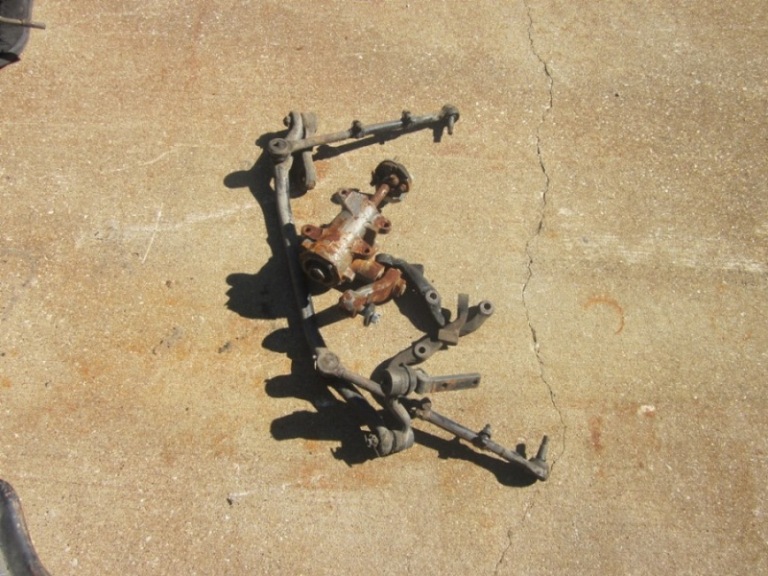
Remove all old steering assembly including steering arms.
Remove Drivers Side motor mount.
Remove front Lower A arm bolts
Layout lines from templates supplied (use level)
Center Punch 3 ea. holes for Hole Saw cut outs
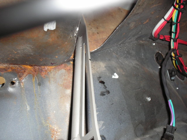
Cut off support bracket for front cross member ( runs front to rear)
Cut off Front cross member where you have marked with templates (this will be taking out about 21”)
Test fit your new cross member and insert bolts where you have removed the lower front A arm bolts. Trim if you need to and weld if you want to along top ridge. (welding not required)
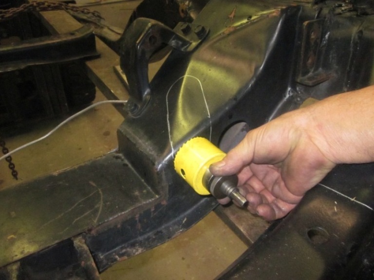
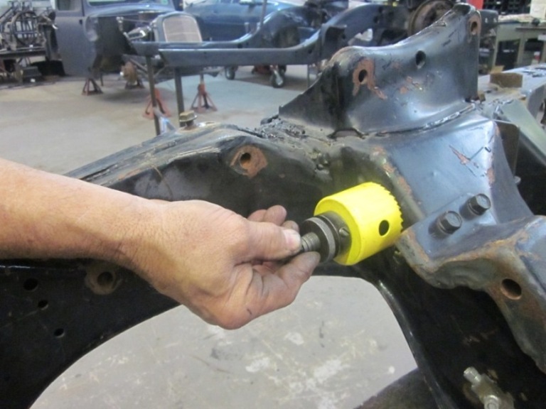
Drill pilot holes for 2 ¼ hole saw/ 3 locations 2 on top front of K member and one on the rear. (for steering shaft run thru)
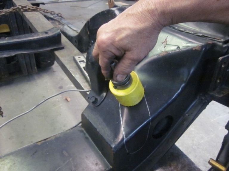
Hole saw same locations
Cut out area between the holes you have just cut per the provided template you have already laid out.
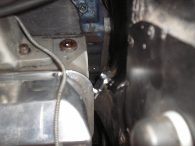
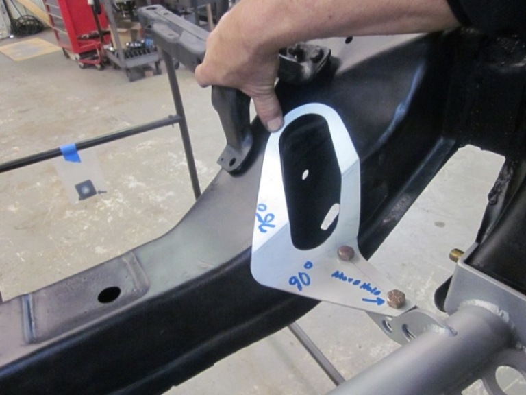
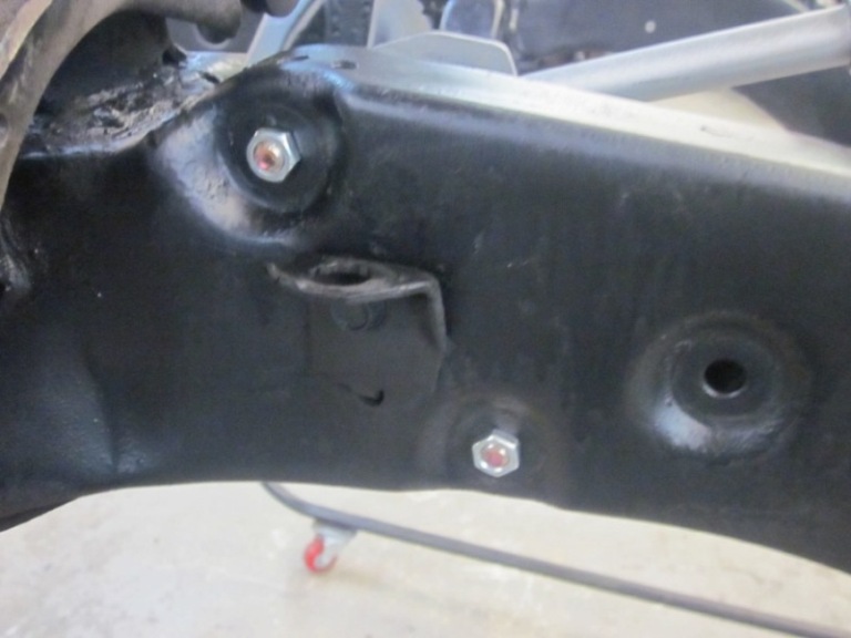
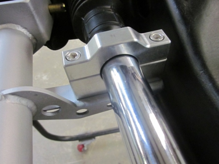
Install Steering mount bracket to frame with supplied bolts all the way thru the frame (existing holes) and install and tighten nuts as required.
(Note: This bracket has slots for some adjustability so align as required)
Assemble steering shaft as shown and secure bolts and slide thru new location holes.
Slide Rack onto new mount to trial fit on to new steering joints. (make sure you have proper clearance. (Note: Rack must be loose in order for the rack can receive new steering u joint) Do not tighten rack before assembly to help line everything up.
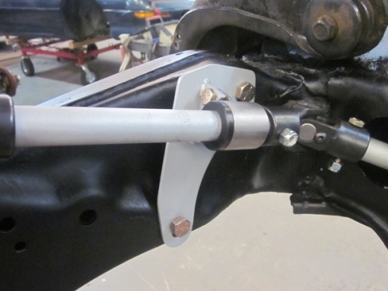
Install rack with new aluminum rack mount brackets, left side only. The right side will bolt directly to the crossmember.
You may at this time tighten up rack and turn steering shaft to check fitment.
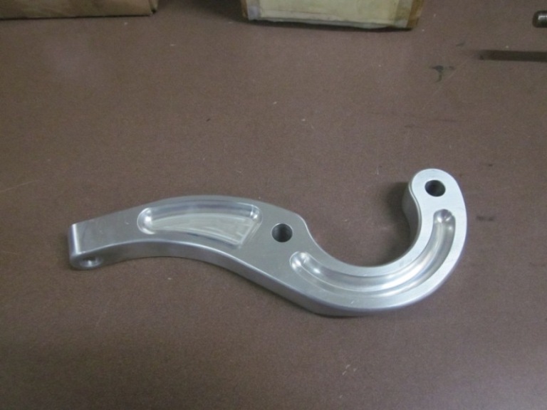
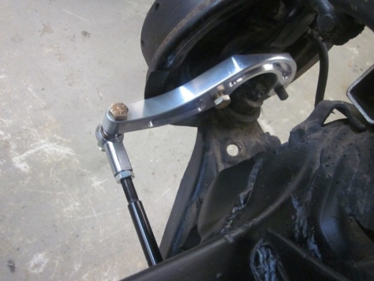
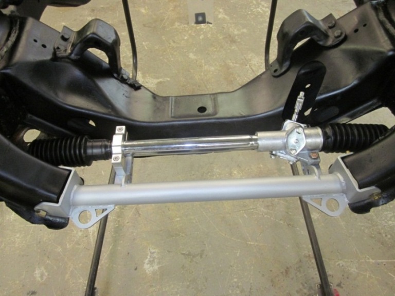
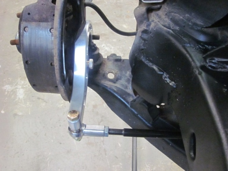
Install steering arms facing towards front of car and install high mis-alignment rod ends to new aluminum steering arm ends and rack.
Note: Check for rubber boot clearance as some times you may have to trim a small amount of clearance so the boot does not rub. Turn steering back and forth and look at the boot area closely and trim with small hand grinder if required.
You may at this time complete your final assembly and check all bolts and all clearance. It should turn smooth with no binding etc. Torque all bolts as required. You may want to remove all parts and powder coat or paint as required at this time.
A steering column modification will be needed in order to complete this install to the 3/4 shaft.Cut off rag joint and slide new shaft “inside” existing steering column. You may at this time drill steering column and shaft and install supplied single bolt. You may weld if desired.
( Note before the above task is done make sure your steering wheel/alignment is set and straight as you require for steering wheel placement.) Also Some Modification required when using Factory Control arms.
You may return new, unopened items within 30 days of ship date for a full refund. Items should be returned in their original product packaging. We'll also pay the return shipping costs if the return is a result of our error. If the item has been opened or is out of original packaging there is a 25% restocking fee. Item must be shipped using prepaid shipping; we will not accept C.O.D. If, upon examination, all parts are returned and all parts are in a like-new condition a refund will be issued less shipping charges using original payment method.
Note: Any damaged or missing parts must be claimed within the 30 day return period.
We are a family owned & operated business started in 1982. All products are made right in our shop by Americans. We work hard everyday to produce the highest quality in welding, material and design for you. Form and function are the most important part of innovative design. We do not sell anything from a foreign country. We could easily outsource our products and bring you some of these parts for less money and sacrifice quality and safety. We make no compromises, we do what it takes to get the job done right. We are just like you, a bunch of hard working guys that want to have a job. We want to do the very best job for you.
Thanks for visiting our web site and keep us on your favorites and we will keep bringing you innovative parts built with the utmost of care and quality.
Thanks to all who have purchased from us. We look forward to working with you.
All parts are made In House with help of our partner company.


The Online Shopping System is currently being upgraded.
To place orders please call: (214) 330-0660
We appreciate your business and are standing by to help with any orders!